

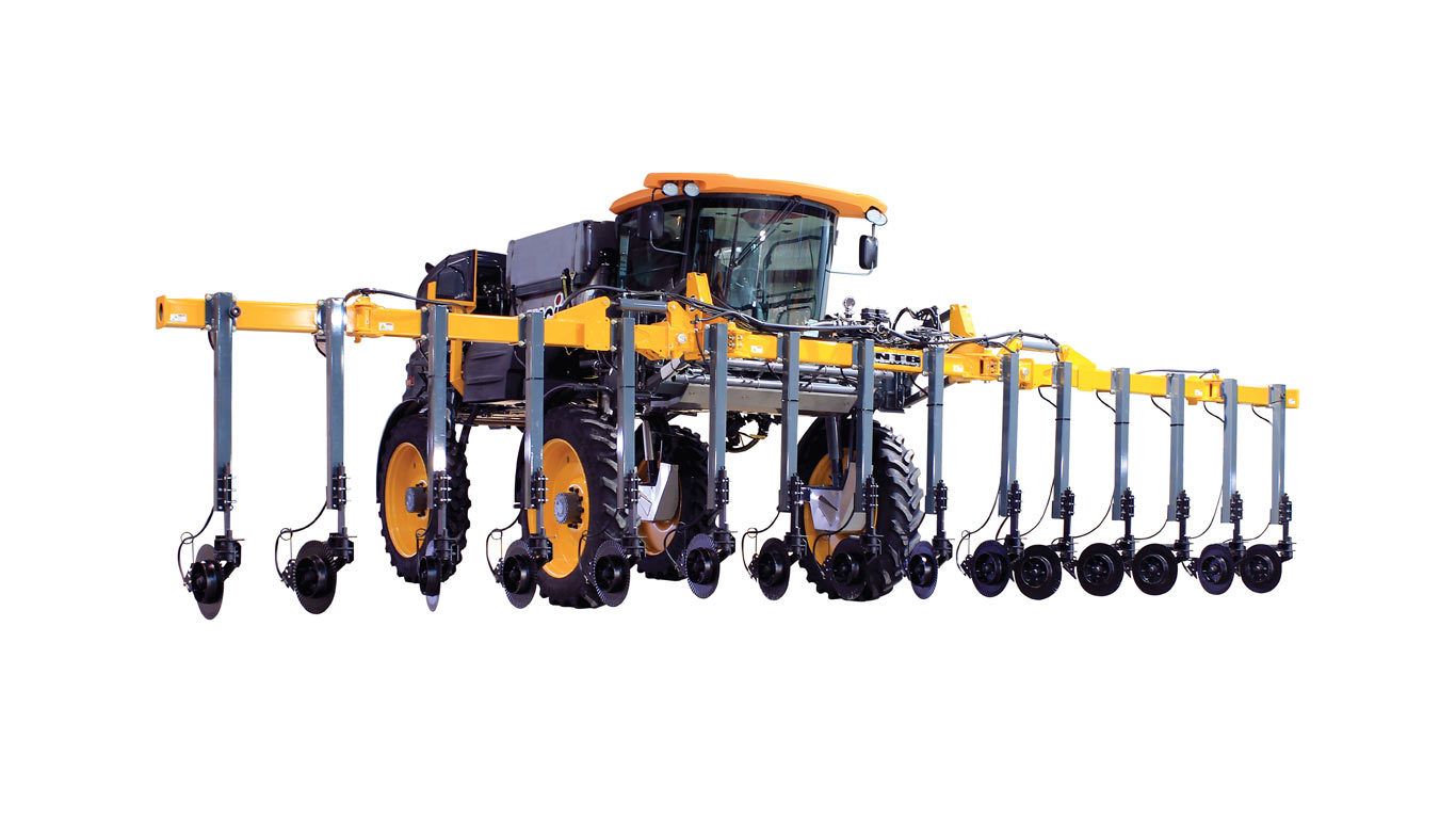
STS10 Overview
- One machine, full-season versatility
- State-of-the-art, SkyKlone air filtration system
- All-wheel steer (optional) reduces turn radius
- Perform late-season applications with Tall Corn Package
John Deere Precision Ag Technologies
STS10 Features
Features
STS Series cab and controls overview
Front console
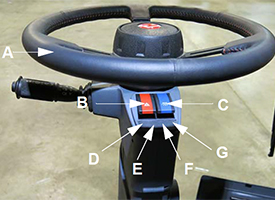 Front console steering
 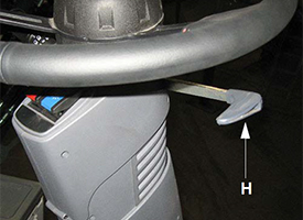 Front console telescope
 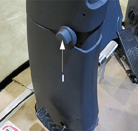 Front console tilt
 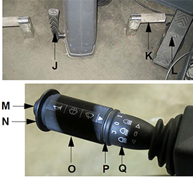 Front console foot controls
 | Location (image) | Component | Description/notes |
| A | Steering wheel | Optional premium leather-wrapped steering wheel |
| B | Hazard/warning lights switch | --- |
| C | Highway/warning lights switch | --- |
| D | Turn signal indicator | Left-hand side |
| E | Highway running lights indicator | --- |
| F | High beams indicator | --- |
| G | Turn signal indicator | Right-hand side |
| H | Steering wheel telescope adjust handle | Available only if equipped with this option |
| I | Steering column tilt adjust button | Knee angle Available only if equipped with this option |
| J | Steering column release pedal | --- |
| K | Operator foot pegs | Two pegs Available only if equipped with this option |
| L | Deceleration (decel) pedal | --- |
| M | Horn | --- |
| N | Windshield washer | --- |
| O | Turn signal lever | --- |
| P | Windshield wiper speed | --- |
| Q | High beams (brights) | --- |
Side console


| Location (image) | Component | Description/notes |
| A | Emergency stop (e-stop) switch | The e-stop switch provides a quick and positive method for stopping the engine in an emergency situation. |
| B | Foam marker switch (if equipped) | The foam marker switch controls foam application on both sides of the machine. |
| C | Rinse switch | The rinse switch is used to rinse the solution tank and spray booms. |
| D | Boom solution valve switches | The boom solution valve switches each control a valve located on the boom or transom. The valves control the flow of the solution through the boom. |
| E | Fence row switch (left-hand side) | The fence row switches are used in the selection of either the right or left fence row spray nozzle. |
| F | Rate control switches | The rate control switches control the rate in which solution is applied through the spray booms by either the rate controller (enable) or operator-controlled spray rate (manual). |
| G | Rear nozzle switch | The rear nozzle switch controls the two rear nozzles (located behind the rear tires). |
| H | Pump speed and rate switches | The pump speed/rate switches allow the user to increase or decrease flow rate through the spray system. |
| I | Fence row switch (right-hand side) | --- |
| J | Main tank valve switch | The main tank valve switch controls the solution tank valve. This switch must be in the on (open) position for spray application. |
| K | Solution pump switch | The solution pump switch is used to turn the solution pump on/off. |
| L | Agitation valve switch | The agitation valve switch controls the rate of flow through the agitation system. |
| M | Boom extension switches (left/right outer fold) | The boom extension switches are used to extend or retract the outer boom extensions. |
| N | Ignition switch | --- |
| O | Power mirror switch (if equipped) | The power mirror switch allows adjustment of the electric side-view mirrors vertically or horizontally by pressing the switch in the desired position. |
| P | Hydrostatic drive control handle | The hydrostatic drive control handle controls the direction of the machine and the speed in which it travels. It is also used to control the spray booms, master spray, end row management, and shift up/down speeds. |
| Q | Transom switch (up/down) | The transom switch is used to raise and lower the main lift. |
| R | Left-hand boom switch | The left- and right-hand boom switches are used to raise, lower, extend, and retract the spray booms. |
| S | Right-hand boom switch | The left- and right-hand boom switches are used to raise, lower, extend, and retract the spray booms. |
| T | Master spray switch | The master spray switch activates the boom solution valves. |
| U | End row management switch | The end-row management switch is a programmable switch that enables various functions (i.e. all-wheel steer, auto steer, master spray, and NORAC® system enable) when the switch is depressed. End-row management settings are programmed through the machine display. |
| V | Shift up switch | The shift up/down switches are used for speed range selection. |
| W | Shift down switch | The shift up/down switches are used for speed range selection. |
| X | Parking brake switch | The parking brake switch is used to engage and disengage the parking brake, as well as extend and retract the ladder. |
| Y | Throttle switch | The throttle switch is used to control engine speed (rpm). |
| Z | Remote stereo controls | The remote stereo controls are conveniently located to control the stereo (volume, mute, source, and seek). |
| AA | 12-V power ports | Four power ports are provided for the connection of additional items (such as radios and computer equipment). |
| BB | Two auxiliary audio input connections | The auxiliary audio input allows connection of a personal iPod® device or MP3 player. |
Overhead monitors and controls
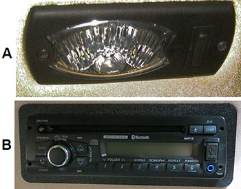
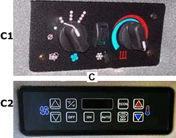
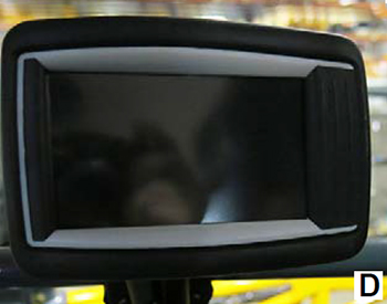

| Location (image) | Component | Description/notes |
| A | Courtesy/interior work light | The courtesy light comes on automatically when the cab door is opened. The interior work light is activated by manually pressing the interior work light switch (located on the light housing). |
| B | Stereo (if equipped) | The stereo features an AM/FM tuner, weatherband broadcasting, CD player, MP3 player, USB/iPod device controls, and Bluetooth® wireless system (if equipped). |
| C | Climate controls | The climate controls allow the operator to set and maintain desired cab temperature. Vents are placed throughout the cab to keep air circulating and to maintain clear windows throughout the cab. |
| D | NORAC monitor (if equipped) | The NORAC monitor controls the automatic boom leveling system. |
| E | Spray system console | The spray system is controlled by the spray system console and the solution pump control valve. The system receives data and automatically makes adjustments based on the target rate of application set by the operator. |
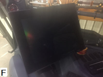
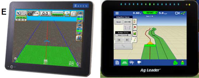
| F | Machine display | The machine display is the central control center of the machine. It controls many of the machine’s electronically-driven functions (i.e. machine drive, AWS, attachment operation, tread adjustment, spray systems, lights, diagnostics, etc.). The sprayer can be configured with one of the following displays: John Deere GreenStar™ 3 2630 Display, Raven Viper® 4+ Display or Ag Leader® InCommand™ 1200 Display |
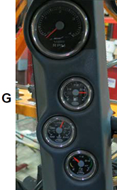
| G | Machine gauges | The machine gauge panel on the A-post is conveniently located for viewing engine rpm, fuel level, engine coolant temperature, and engine aftertreatment level (if equipped). |
iPod is a trademark of Apple, Inc. NORAC is a trademark of NORAC Systems International. Bluetooth is a trademark of Bluetooth SIG Incorporated. Viper is a trademark of Raven Industries Incorporated. Ag Leader and InCommand are trademarks of Ag Leader Technology, Inc.
Hagie™ STS Series engines
6.7-L Cummins® QSB engine
 Final Tier 4 engine
  Tier 3 engine
 The Hagie STS Series is powered by a 6.7-L (408.9-cu in.) Cummins QSB diesel engine, which is offered in a 202-kW (275-hp) Tier 3 or the 220-kW (300-hp) emissions-compliant Final Tier 4 (FT4) configuration. The engine is electronic with an air-to-air cooler and turbo charger.
The Tier 3 engine requires No. 2 diesel fuel, and the FT4 engine requires ultra-low sulfur diesel (ULSD).
Engine location
 Rear-mounted engine
 The rear-mounted engine keeps constant weight to offset the spray boom and leaves space in the center of machine for the varying weight of fuel and rinse tanks. This allows for better coolant airflow and reduction of cab noise.
Engine exhaust
 Rear-located engine exhaust
 The engine exhaust is located at the rear of the machine. This helps to reduce interior cab and noise vibration.
Cummins is a trademark of Cummins Incorporated. Hagie is a trademark of Hagie Manufacturing Company, LLC and similar to John Deere branded equipment, John Deere will also support Hagie equipment.
Frame and axles
 Chassis mainframe
 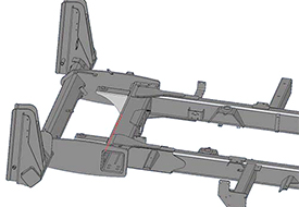 Horizontal cross-through axle tube
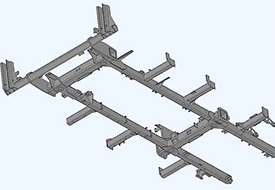
 The STS Series mainframe design features horizontal cross-through axle tubes, as well as boom and platform mounts on weldment.
- 144.8-cm (57-in.) mainframe width (from outside of each mainframe tube)
- 301-cm (118.5-in.) mainframe width (from outside of each boom cradle weldment)
- 188-cm (74-in.) ground clearance
Solution tank, pump, and pump switch
The solution system is a constantly monitored, continuously adjusted, computer-controlled system. The cab-mounted digital spray system console receives information from various inputs to help determine L/ha (gpa) and L/min (gpm).
Solution tank
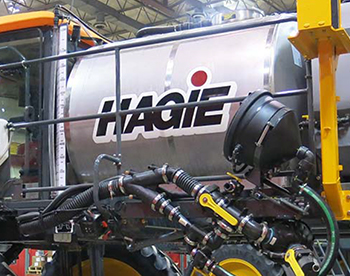 Solution tank
 | Sprayer model | Tank capacity (L, gal.) | Tank type |
| STS10 | 3785 L (1000 gal.) | Standard - polyethylene tank Optional - stainless-steel tank |
| STS12 | 4542 L (1200 gal.) | Stainless-steel tank |
| STS14 | 5299 L (1400 gal.) | Stainless-steel tank |
| STS16 | 6056 L (1600 gal.) | Stainless-steel tank |
Solution pump
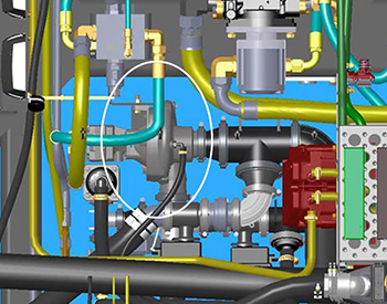 Solution pump
 The Hypro® 9306C-HM1C-BU solution pump (located beneath center of machine) is a centrifugal-type, hydraulically-driven pump that is controlled by the solution pump control valve and the spray system console. It comes with silicon-carbide seals, 7.6-cm (3-in.) inlet plumbing and 5.1-cm (2-in.) outlet plumbing.
The solution pump draws solution out of the tank at the rate determined during calibration. It dispenses solution through the many valves and hoses that make up the spray system and also dispenses fluids through the agitation and rinse systems.
Solution pump switch
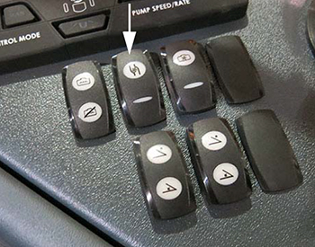 Solution pump switch
  Solution pump indicator
 The solution pump switch is located on the side console and is used to turn the solution pump on and off.
NOTE: When the solution pump is on, a solution pump indicator (located on the machine display home page - field mode) will be illuminated.
Hypro is a trademark of Pentair Flow Technologies, LLC.
STS™ Series spray booms
 STS Series Sprayer booms
 The spray booms are controlled by an electrohydraulic system. This system consists of operator-manipulated switches (located on the side console and the hydrostatic drive control handle) and hydraulic cylinders (attached to the booms), which provide lift, level, and horizontal extension.
The spray booms are offered in a variety of configurations depending on the model and the producer's application needs.
27.4-m (90-ft) boom with 38.1-cm (15-in.) row spacing

Numerical values key:
- Section one
- Section two
- Section three
- Section four
- Section five
- Section six
- Section seven
- Section eight
- Section nine
Alphabetical values key:
- 18.3-m (60-ft) 24-row planter
- 9.1-m (30-ft) 12-row planter
- 9.1-m (30-ft) 12-row planter
- 9.1-m (30-ft) 12-row planter
Boom configurations
| STS Series model | Boom location | Minimum boom width (m, ft) | Maximum boom width (m, ft) | Number of boom sections | Wet boom nozzle spacing (cm, in.) |
| STS10 | Front | 18.3 or 27.4 m (60 or 90 ft) | 36.6 or 40.2 m (120 or 132 ft) | Nine | 38 or 51 cm (15 or 20 in.) |
| STS12 | Front | 18.3 or 27.4 m (60 or 90 ft) | 36.6 or 40.2 m (120 or 132 ft) | Nine | 38 or 51 cm (15 or 20 in.) |
| STS14 | Front | 18.3 or 27.4 m (60 or 90 ft) | 36.6 or 40.2 m (120 or 132 ft) | Nine | 38 or 51 cm (15 or 20 in.) |
| STS16 | Front | 18.3 or 27.4 m (60 or 90 ft) | 27.4 or 36.6 m (90 or 120 ft) | Nine | 38, 46, 51, or 76 cm (15, 18, 20, or 30 in.) |
Materials used in boom construction:
- 27.4-m/30.5-m (90-ft/100-ft) booms - steel
- 36.6-m (120-ft) booms - steel/aluminum hybrid
- 40.2-m (132-ft) booms - aluminum
30.5-m (100-ft) boom with 38.1-cm (15-in.) row spacing

Numerical values key:
- Section one
- Section two
- Section three
- Section four
- Section five
- Section six
- Section seven
- Section eight
- Section nine
Alphabetical values key:
- 18.3-m (60-ft) 24-row planter
- 3.05 m (10 ft)
- 9.1-m (30-ft) 12-row planter
- 9.1-m (30-ft) 12-row planter
- 9.1-m (30-ft) 12-row planter
- 3.05 m (10 ft)
36.6-m (120-ft) boom with 38.1-cm (15-in.) row spacing

Numerical values key:
- Section one
- Section two
- Section three
- Section four
- Section five
- Section six
- Section seven
- Section eight
- Section nine
Alphabetical values key:
- 9.1 m (30 ft)
- 18.3-m (60-ft) 24-row planter
- 9.1 m (30 ft)
- 9.1-m (30-ft) 16-row planter
- 9.1-m (30-ft) 16-row planter
- 9.1-m (30-ft) 16-row planter
- 4.6 m (15 ft)
- 9.1-m (30-ft) 12-row planter
- 9.1-m (30-ft) 12-row planter
- 9.1-m (30-ft) 12-row planter
- 4.6 m (15 ft)